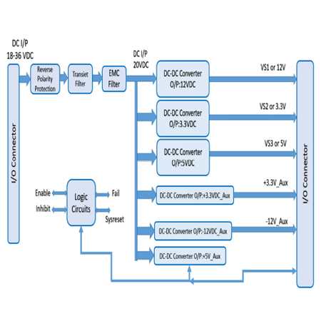
Enable, inhibit, system reset and power fail controls
Remote voltage sense: VS1, VS2, VS3
Build to meet Military Standards MIL STD 704F, MIL STD 461F, MIL STD 810G
Technical Specifications
DC Input
28VDC Nominal I/P
18 to 36 VDC Range
MIL-STD-704 (A-F) Normal and Abnormal Steady State
MIL-STD-704(A-F) transients Up to 50V, 80V.
MIL-STD-704(A-F) Transients Under 18V and Starting transients.
DC Output Voltages & Current
VS1: 12V, up to 20A
VS2: 3.3V, up to 25A
VS3: 5V, up to 25A
12V_Aux: 12V, up to 2A
-12V_Aux: -12V, up to 1A
3.3V_Aux: 3.3V, up to 5A
Ripple and Noise
Typically, less than 100mVp-p.
Measured across a 0.1μF capacitor and 47μF/63V
With the Shortest Ground loop and PSU Connector End capacitor with on load at Input Voltage of 28VDC
Bandwidth Set limit of 20Mhz
Special Features
VITA 62 Compliant
Wide Input Range
Remote Senses (VS1,VS2&VS3)
Output short circuit Protection
DC I/P Reverse Polarity protection
Over temperature shutdown with auto-recovery
EMI filters included
I2C communication
EMI/EMC
Build to meet with MIL-STD 461F (CE101, CE102, CS101, CS114, CS115, CS116
Efficiency
Up to 80-85 % (At Full load room temperature)
Environmental
Design to Meet MIL-STD-810G
Temperature (Operating: –40°C to +85°C, Storage: –40°C to +100°C)
Altitude (3,000m (10,000feet) max)
Humidity (Up to 95% RH)
Fungus (As Per Mil Std 810G)
Shock (As Per Mil Std 810G )
Vibration (As Per Mil Std 810G )
Salt Fog (As Per Mil Std 810G)
Isolation
Input to Output: DC1500V or AC1,000V 1minute, Cut off current = 10mA
Input to Case Ground: DC1000V or AC1,000V 1minute, Cut off current = 10mA,
Output to Case Ground: DC1000V 1minute, Cut off current = 10mA,
Functions and Signals - According to VITA 62
Sl. No.
Signal Name
Type
Description
1
FAIL*
Output
Indicates to other modules in the system that a failure has
occurred in one of the outputs. Please refer to Figure 2
This signal is referenced to SIGNAL RTN.
2
SYSRESET*
Output
Indicates to other modules in the system that all outputs are
within their working level. Please refer to Figure 2
This signal is referenced to SIGNAL RTN.
3
INHIBIT*
Input
Controls power supply outputs.
This signal in conjunction with INHIBIT controls the outputs
Please refer to Table 1 and Figure 1
This signal is referenced to SIGNAL RTN
4
ENABLE*
Input
Controls power supply outputs.
This signal in conjunction with INHIBIT controls the outputs.
Please refer to Table 1 and Figure 1
This signal is referenced to SIGNAL RTN.
5
VOUT
REMOTE
SENSE
Input
The SENSE is used to achieve accurate load regulations at load
terminals (this is done by connecting the pins directly to the
load’s terminals).
Inhibit and Enable Functionality
INHIBIT*
Low
Low
High
High
ENABLE*
Low
High
Low
High
VS1,VS2,VS3,±12VAux
OFF
OFF
ON
OFF
+3.3VAux
ON
OFF
ON
OFF
I/O Connector Pin Details
Pin
Function
Description
P1
28VDC_RET
DC Input Voltage Return
P2
28VDC_POS
DC Input Voltage
LP1
Chassis GND
Chassis Gnd
A1
Status Signal
PSU Function Status Signal-1
B1
Status Signal
PSU Function Status Signal-3
C1,D1,A2
NC
Not Used
B2
FAIL
Indicates to other modules in the system that a failure has
occurred in one of the outputs.
C2
INHIBIT
Input control signal as defined in VITA 62, referenced to
SIGNAL_RETURN
D2
ENABLE
Input control signal as defined in VITA 62, referenced to
SIGNAL_RETURN
A3
Status Signal
PSU Function Status Signal-2
B3
+12V_Aux
+12V auxiliary output voltage
C3,D3
NC
Not Used
A4
+3.3V_Aux
+3.3V auxiliary output voltage
B4
+3.3V_Aux
+3.3V auxiliary output voltage
C4
+3.3V_Aux
+3.3V auxiliary output voltage
D4
+3.3V_Aux
+3.3V auxiliary output voltage
A5,B5
NC
Not Used
C5
PSU_SCL
I2C Communication Bus for PSU Status-Spare
D5
PSU_SDA
I2C Communication Bus for PSU Status-Spare
A6
PSU_SCL1
I2C Communication Bus for PSU Status
B6
PSU_SDA1
I2C Communication Bus for PSU Status
C6
-12V_Aux
–12V auxiliary output voltage
D6
PSU_SYSRESET
Indicates to other modules in the system that all outputs are
within their working level.
A7,B7,C7
NC
Not Used
D7
Signal_RTN
Ground pin for control signals
A8
VS1_S+/12V
VS1 sense, should be connected at point-of-load or on the
backplane to corresponding voltage output
B8
VS2_S+/3.3V
VS2 sense, should be connected at point-of-load or on the
backplane to corresponding voltage output
C8
VS3_S+/5V
VS3 sense, should be connected at point-of-load or on the
backplane to corresponding voltage output
D8
Sense_RTN
Should be connected to Common output Ground Rtn at the
connector
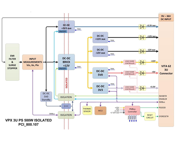
Isolated 3.3V aux,12V aux and 5V auxstandby feature
350W Maximum Power
95% Typical Efficiency
-55°C to 95°C Rail Operating Temperature
VITA 62 3U Form Factor
SMART Function
VITA 62 3U ISOLATED 350W 28VDC POWER SUPPLY
This 3U power supply works with 9Vto 36 VDC (28VDC nominal) input voltage and isolates the input voltage ground from the output voltage ground. The power supply is conduction cooled, uses polyphase technology on all voltage rails and can provide up to 350 watts. It is suitable for use in mission critical rugged applications
Intelligent power supplies integrate a microcontroller (MCU) for a fully programmable and flexible solution. Intelligent power conversion allows configuration and reconfiguration for different applications. With intelligent power conversion, the power supply becomes a platform solution for Vita 46.11 system management-based systems. The power supply can easily be reprogrammed to support different operating limits and control inputs.
Features
Parallel operating with multiple power supplies, all rails
Load sharing and balancing
Digital On/Off control for low standby power
Spread Spectrum Clocking of power supply stages
Possibility of external synchronization
Power supply sequencing and hot-swap control
Power supply history logging and fault management
Monitoring all input/output voltages, currents and power
Current fold back control
Automatic temperature drift compensation for all outputs
Efficiency calculations at any time
Communication via SMB/I2C (PMB)for Vita 46.11 system management
Collects data from temperature sensors for over temperature protection
Precision compensation of all output voltages using integrated 5ppm voltage reference
Overview
VITA Compliant
VITA62
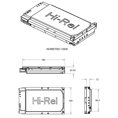
Size
3U
Temp. Range
-55 +95 C
Input (AC or DC)
DC
Input Range (VDC)
9-40
Active EMI Filtering
YES
Efficiency (%, typ.)
95
# of outputs
6
FEATURES
Over-current Protection
YES
Over-voltage Protection
YES
Over-temperature Protection
YES
Current Sharing
VS1, VS2, VS3
Remote Sense
YES
Standard Control
YES, VITA62
OUTPUTS (Total output not to exceed
350W)
VS1, V@A
+12@10A
VS2, V@A
+3.3@25A
VS3, V@A
+5@30A
AUX, V@A
+3.3@4A
AUX, V@A
+12@1.5A
AUX, V@A
-12@1.5A
COMPLIANCE
MIL-STD-461
YES
MIL-STD-810G
YES
* ESD Protection
YES
* Shock
YES
* Vibration
YES
* Rapid Decompression
YES
Corrosion Resistance
YES
* Fungus Resistance
YES
* Altitude
YES
* Humidity
YES
INPUT CHARACTERISTICS
Parameter
Min
Typ
Max
Units
Notes
Absolute Maximum
Ratings
Input Voltage
- Non-Operating
-60
60
V
Continuous
- Operating
-40
40
V
Continuous- Reverse input
Protection
- Operating Transient Protection
50
v
100ms transient, square wave
Isolation Voltage
150
V
Operating Temperature
-40
85
c
Storage Temperature
-55
105
C
Electrical Characteristics
Input Voltage
- Continuous
9
40
V
- Transient
9
48
V
50V Transient for 100 ms
Under-Voltage Lockout
-55
105
C
- Turn-On Input Voltage Threshold
8.5
9
10
V
OUTPUT
CHARACTERISTICS
Parameter
+12V
+5V
+3.3V
+3.3V aux
+12V aux
-12V aux
Notes
Output Voltage Set Point, V
12
5
3.3
3.3
+12
-12
Vin = 28V
- Drift -40 deg.C to 85degC +/-
0.01
0.01
0.01
0.01
0.01
0.01
Vin = 28V
Output Voltage Trim Range, V
12
5
3.3
3.3
+12
-12
Over Line/load/temp
+/-10%
+/-10%
+/-10%
+/-10%
+/-10%
+/-10%
Over Line/load/temp
Output Voltage Ripple (pk-pk), mV
80
50
40
40
80
80
Full load with 1 uF + 10 uF tantalum capacitor
Operating Current Range, A
0-40
0-40
0-20
0-4
0-1.5
0-1.5
Over-Voltage Protection, V
13
6
3.6
3.6
13
13
Current Limit Inception, A
42
42
22
5
1.7
1.7
Current Limit Inception, A 42 42 22 5 1.7 1.7 Maximum Output Capacitance,mF
10
10
10
1
1
1
Block Diagram
Get in Touch Now
Book a Demo call with our consultant
and let us assist you with your
requirements.
If you’d like a quote or would like to talk to us, please fill in the form below. Alternatively, you can call us on +91 80 2955 8280 (IND) or +44 7914 935648 (UK)